In this project, the two sections I chose to implement were Part 1: Mirror and Glass Materials and Part 4: Depth of Field. Implementing the reflection and refraction functions helped give me a better intuition for how light bounces off and moves through different surfaces than just seeing diagrams and formulas in lecture. I enjoyed implementing the depth of field effect, allowing me to change variables like the aperature and focal distance, because it gave me a chance to experiment with different combinations of parameters to produce more artistic renders.
Part 1: Mirror and Glass Materials
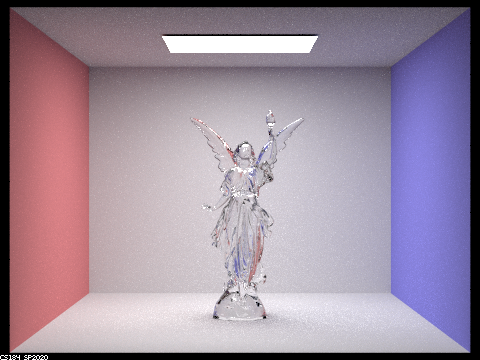
In this part, I implemented reflection functions for mirror and glass materials and a refraction function for glass material. For mirror materials, incoming light rays are directly reflected off. For glass materials, rays are both reflected and refracted. Refraction must take into account the differing indices of refraction of the two materials and determine whether the ray is entering or exiting the non air material. Since both reflection and refraction occur, we use Schlick's approximation to esimate the ratio of reflection to refraction energy and find a probability of either reflecting or refracting for each sample. There is also the case of total internal reflection, where refraction does not occur.
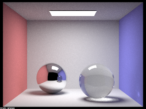
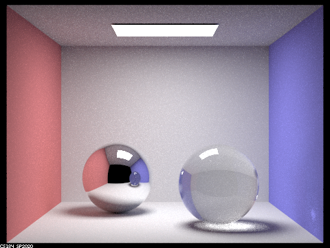
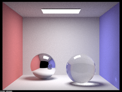
These images were created with parameters 256 samples per light, 4 samples per area light, resolution 480x360 pixels and a given ray depth.

|
|
|
|
|
|
|
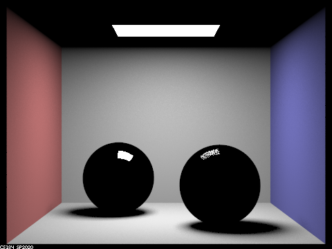
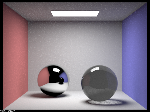
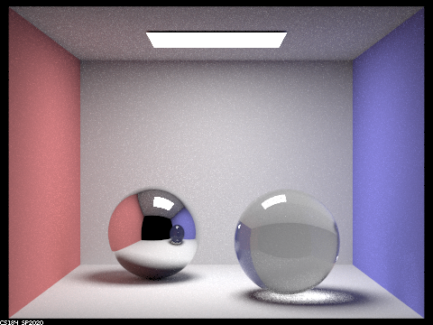
Comparing renders with different ray depths, we can see the emergence of new multibounce effects on these mirror and glass spheres. With ray depth of 0, the scene is not visible because we only render emitted light (rays of light directly from the light source to the camera). With a ray depth of 1 (1 bounce), we can see the spheres, walls, shadows and reflection of the light source on the spheres. With a ray depth of 2 (2 bounce), we can see reflection of the walls and other sphere in the spheres and a more complicated shadow for the glass sphere. As the ray depth continues to increase, we see more details; for example, the reflection of the glass sphere in the mirror sphere goes from being opaque with ray depth 2 to obviously glass by ray depth 100 and we can begin to see the effects of refraction and total internal reflection at ray depth 3. At ray depth 4, we can see a bright patch on the right wall which is a result of the light source being refracted through the glass sphere.
Part 4: Depth of Field
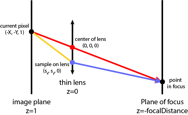
In this part, I implemented depth of field options, allowing variable aperture and focal length. All of the previous renders done in this project used a pinhole camera model, so the entire image was in focus (infinite depth of field) and the aperture (camera lens radius) only allowed a single ray through at a time (value of 0). The human eye and real life cameras have finite dimensions; objects we are focusing on are sharper than other objects in the field of view, and it is possible to change the lens radius, which affects how much light enters the camera. In this part, we use the thin lens camera model as seen in the above diagram; light can refract through the lens but we ignore the actual thickness of the lens.
In the ray generation function, the aperture affects the size of the lens plane along which a point is sampled (blue dot in diagram). This point is pLens. We calculate a ray from the current pixel (black dot on the image plane) through the center of the lens (red in the diagram). The intersection between this ray and the focus plane (at a distance of focalDistance from the camera) is the point pFocus (black dot on the plane of focus). We return a normalized world space ray from pLens in the direction of pFocus (transformed blue ray).

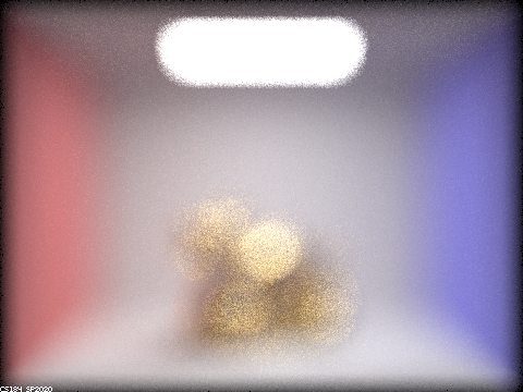
Decreasing aperture size increases the depth of field, making more of the image appear sharper.
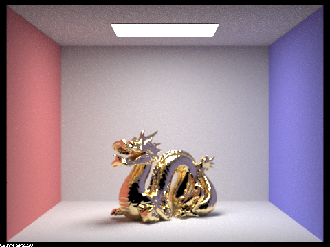
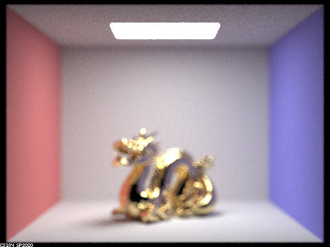
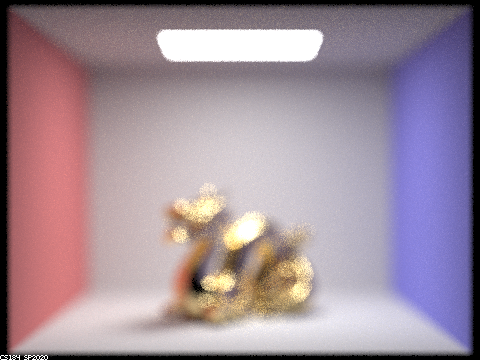
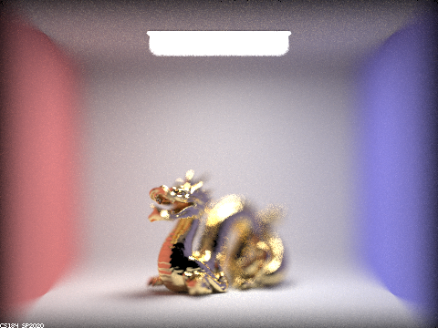
The following images were rendered with with parameters 256 samples per light, 4 samples per area light, resolution 480x360 pixels, max ray depth of 5, focal distance of 3.26, and variable lens radius (aperture).
|
|
|
|
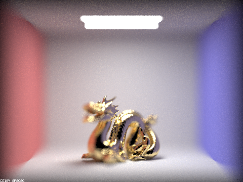
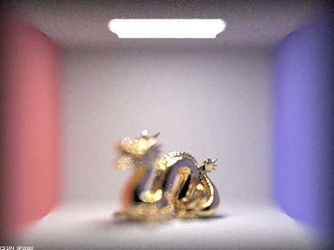
Changing focal distance allows us to focus on parts of the scene at different depths. A larger focal distance focuses on parts further away from the camera.
The following images were rendered with with parameters 256 samples per light, 4 samples per area light, resolution 480x360 pixels, max ray depth of 5, lens radius of 0.5, and variable focal distance.
|
|
|

|